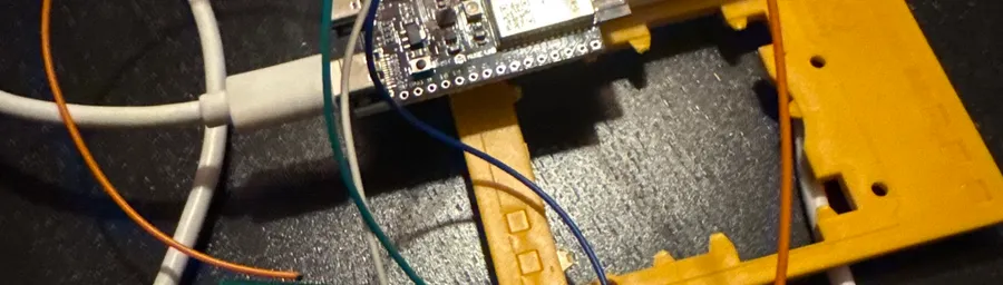
Smart Blinds on the Cheap: Hacking a Somfy Telis 4 RTS with an ESP32-C6
How I wired an ESP32-C6 into two Somfy remotes to control my blinds and awning from Home Assistant. No RF module required.
I wanted smart blinds. I didn’t want to replace the motors or buy an expensive hub. So I cracked open my Telis 4 RTS remote, soldered a few wires to the buttons, and let an ESP32-C6 do the pressing. Then I did the same thing with the awning remote. Both on one ESP32.
The idea
The Somfy RTS protocol runs on 433.42 MHz — an unusual frequency that most off-the-shelf RF modules don’t support. You can emulate it with a CC1101 transceiver, but that means extra hardware, a library to wrangle, and you still have to pair the new transmitter with your motors. More moving parts than I wanted.
The simpler approach: skip the radio entirely. Wire an ESP32 directly to the physical buttons on the remote’s PCB. Pull a pin LOW, the Telis sends its RF command, blinds move. The remote handles all the protocol stuff. I’m just automating the finger press.
Mapping the buttons
The Telis 4 has three tactile buttons (UP, STOP, DOWN) connected to a central IC. Each button has four legs, internally just two pairs, bridged when pressed. To figure out which leg is signal and which is ground, I used a multimeter in continuity mode and probed across legs until I found which ones were shared between buttons. Those are ground.
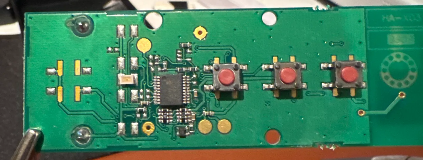
The slightly annoying part: the ground side alternates between buttons.
- UP: ground on top legs, signal on bottom
- STOP: ground on bottom legs, signal on top
- DOWN: ground on top legs, signal on bottom
The awning remote was cleaner, all the ground legs on the same side. But the process is identical either way: find the shared legs with continuity mode, solder to the other side.
Wiring
One dupont wire per button, soldered to the signal-side leg. Plus one wire to a ground leg for the shared connection.
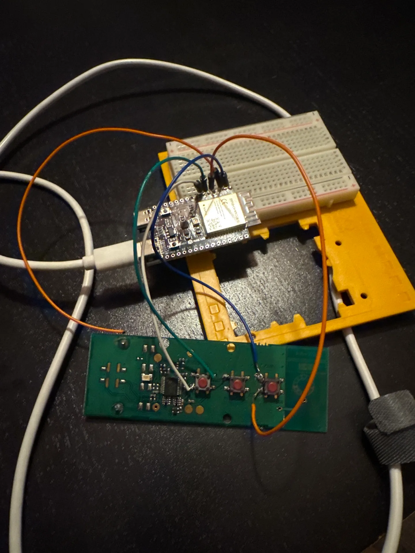
That orange wire looping from the ESP32’s 3.3V pin down to the Telis battery pads was an attempt to power the remote off the ESP32’s rail and ditch the coin cell. More on why that didn’t work below.
Blinds remote
| Wire | Telis PCB | ESP32-C6 |
|---|---|---|
| UP signal | Button 1, bottom leg | GPIO 4 |
| STOP signal | Button 2, top leg | GPIO 5 |
| DOWN signal | Button 3, bottom leg | GPIO 6 |
| Ground | Any ground leg | GND |
Awning remote
| Wire | Awning PCB | ESP32-C6 |
|---|---|---|
| Contract signal | Button 1 | GPIO 7 |
| STOP signal | Button 2 | GPIO 8 |
| Expand signal | Button 3 | GPIO 10 |
| Ground | Any ground leg | GND |
Both remotes share the ESP32’s GND. I spliced the two ground wires together and ran one to the board.
One thing worth knowing: GPIO 0 and 1 on the C6 are strapping pins. If you hold them LOW during boot the chip can get stuck. I had my awning signals on those pins initially and hit weird boot issues until I moved them to 7, 8, and 10.
The power problem
My first attempt was to cut the coin cell out entirely and power the Telis from the ESP32’s 3.3V rail. The voltage measured correctly at the battery pads (3.32V), but the remote just stopped working. Button presses did nothing.
My guess is noise. The ESP32’s onboard regulator is a switching supply, and the Telis RF circuit is apparently sensitive enough that it doesn’t like dirty power. The original CR2430 is clean DC. So: keep the coin cells, share only the ground. A CR2430 lasts well over a year anyway.
Testing with Arduino first
Before setting up ESPHome I flashed a quick Arduino sketch to make sure the GPIO control actually worked. The important bit: leave the pin floating when idle and only pull it LOW to simulate a press. If you drive it HIGH you’re fighting the remote’s internal pull-up and weird things happen.
void pressButton(int pin) {
  digitalWrite(LED_BUILTIN, HIGH);
  pinMode(pin, OUTPUT);
  digitalWrite(pin, LOW);
  delay(150);
  pinMode(pin, INPUT);
  digitalWrite(LED_BUILTIN, LOW);
}
150ms is enough to trigger a full open or close command. Holding longer puts the blinds in “jog” mode — they move only while held and stop when released. Good to know, but not what I was after.
ESPHome config
Once the Arduino test passed I switched to ESPHome. The GPIO switches use OUTPUT_OPEN_DRAIN with inverted: true, which replicates the float-when-idle, pull-LOW-to-activate behavior without any extra logic.
The two time_based cover components give Home Assistant proper cover entities: open, close, stop, and position estimation. The underlying GPIO switches are marked internal so they don’t show up as separate entities on the dashboard.
esphome:
  name: blinds-controller
  friendly_name: Blinds Controller

esp32:
  board: esp32-c6-devkitc-1
  framework:
    type: esp-idf

wifi:
  ssid: !secret wifi_ssid
  password: !secret wifi_password

logger:

api:

ota:
  platform: esphome

switch:
  # Blinds (Remote 1)
  - platform: gpio
    pin:
      number: GPIO4
      mode: OUTPUT_OPEN_DRAIN
      inverted: true
    name: "Blinds Up"
    id: blinds_up
    internal: true
    on_turn_on:
      - delay: 150ms
      - switch.turn_off: blinds_up

  - platform: gpio
    pin:
      number: GPIO5
      mode: OUTPUT_OPEN_DRAIN
      inverted: true
    name: "Blinds Stop"
    id: blinds_stop
    internal: true
    on_turn_on:
      - delay: 150ms
      - switch.turn_off: blinds_stop

  - platform: gpio
    pin:
      number: GPIO6
      mode: OUTPUT_OPEN_DRAIN
      inverted: true
    name: "Blinds Down"
    id: blinds_down
    internal: true
    on_turn_on:
      - delay: 150ms
      - switch.turn_off: blinds_down

  # Awning (Remote 2)
  - platform: gpio
    pin:
      number: GPIO7
      mode: OUTPUT_OPEN_DRAIN
      inverted: true
    name: "Awning Contract"
    id: awning_in
    internal: true
    on_turn_on:
      - delay: 150ms
      - switch.turn_off: awning_in

  - platform: gpio
    pin:
      number: GPIO8
      mode: OUTPUT_OPEN_DRAIN
      inverted: true
    name: "Awning Stop"
    id: awning_stop
    internal: true
    on_turn_on:
      - delay: 150ms
      - switch.turn_off: awning_stop

  - platform: gpio
    pin:
      number: GPIO10
      mode: OUTPUT_OPEN_DRAIN
      inverted: true
    name: "Awning Expand"
    id: awning_out
    internal: true
    on_turn_on:
      - delay: 150ms
      - switch.turn_off: awning_out

cover:
  - platform: time_based
    name: "Blinds"
    open_action:
      - switch.turn_on: blinds_up
    open_duration: 50s
    close_action:
      - switch.turn_on: blinds_down
    close_duration: 50s
    stop_action:
      - switch.turn_on: blinds_stop

  - platform: time_based
    name: "Awning"
    open_action:
      - switch.turn_on: awning_out
    open_duration: 30s
    close_action:
      - switch.turn_on: awning_in
    close_duration: 30s
    stop_action:
      - switch.turn_on: awning_stop
Flashing
The browser-based ESPHome flasher didn’t work with my C6. Command line was fine:
brew install esphome
esphome run blinds-controller.yaml
If the board doesn’t enter download mode automatically: hold BOOT, tap RST, release BOOT, then run the flash command. After the first flash, OTA updates work fine so you won’t need to do this again.
Where it ended up
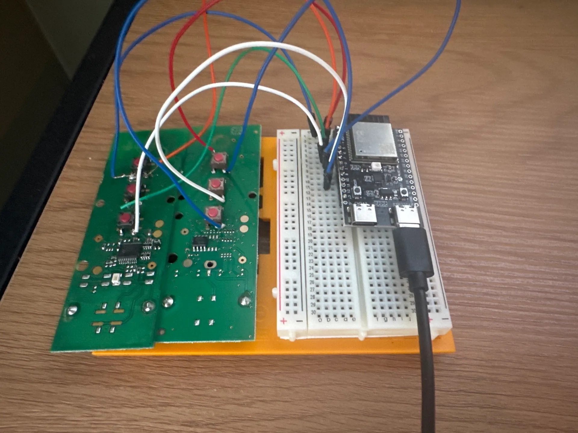
Both remotes show up in Home Assistant as cover entities. Open, close, stop, position estimation — it all works. One ESP32-C6, two remotes, six GPIO pins.
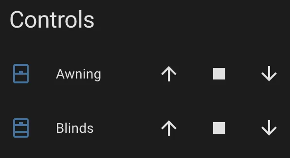
Auto-generated device controls, functional but rough. I’ll swap these out for a proper dashboard card eventually.
What’s left
The breadboard is still sitting there. At some point I want to solder everything directly, design a small enclosure that houses the ESP32 and both remote PCBs (with the buttons still accessible for manual use), and build a proper dashboard card. For now it works and that’s enough.